Selecting the correct operational volume for a DAF wastewater treatment facility stands as a fundamental engineering choice in modern industrial plant design. An undersized unit fails to meet mandatory environmental discharge limits, whereas an oversized installation needlessly inflates capital expenditure and ongoing power consumption. The technical parameters governing DAF wastewater treatment system sizing directly affect daily separation performance, regulatory compliance, and total lifecycle management costs. Evaluating these criteria thoroughly allows facility managers to implement a system customized for their specific liquid waste characteristics.
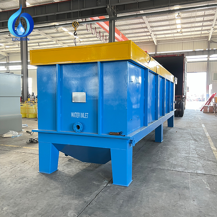
Manufacturing operations generate liquid streams with wide-ranging pollutant concentrations, particle sizes, and flow fluctuations. A commercial DAF wastewater treatment installation must be engineered to handle raw influent variations while maintaining sufficient operational safety margins. Dimensioning requires calculating hydraulic throughput, mass solids loading, micro-bubble air saturation, and tank residence time within a unified specification. Understanding these core dissolved air flotation design parameters helps engineers predict system efficiency across changing industrial conditions.
Hydraulic Volume and Processing Throughput
Managing Peak versus Mean Flow Demands
Hydraulic flow rate defines the hourly liquid volume that a DAF wastewater treatment plant must clear, generally measured in cubic meters per hour or gallons per minute. While mean daily flow establishes basic operational baselines, short-term peak flow dictates actual flotation basin dimensions. Every DAF wastewater treatment unit must absorb temporary surge volumes without compromising internal clarification velocities or causing hydraulic short-circuiting. Peak rates routinely reach 1.5 to 2.5 times the average daily volume, depending on factory washdown cycles and batch discharges. Analyzing hourly flow profiles ensures your primary DAF wastewater treatment infrastructure maintains uninterrupted performance during peak production surges.
Hydraulic Residence Time and Phase Separation
Hydraulic residence time measures how long contaminated water remains inside the DAF wastewater treatment basin for bubble attachment and flotation. Operating residence times usually range from 15 to 30 minutes, determined by contaminant buoyancy and particulate density. Insufficient residence time causes partially separated flocs to escape into the final discharge, lowering overall DAF wastewater treatment efficiency. Conversely, excessive detention time requires larger tank footprints that raise civil construction costs unnecessarily. Correctly engineered DAF wastewater treatment systems strike a balance by providing just enough time for target contaminants—such as free oils, suspended solids, and colloidal fats—to float cleanly to the surface.
Mass Solids Load and Contaminant Composition
Suspended Solids Mass Loading and Sludge Yield
The solids loading rate represents the mass of total suspended solids entering a DAF wastewater treatment vessel per unit of surface area per hour. This variable dictates the physical surface footprint needed for effective phase separation. High-solids industries—including food processing, rendering, and paper manufacturing—require expanded surface areas to avoid surface overloading in their DAF wastewater treatment operations. The floated sludge blanket forming at the surface must be removed at rates matched to downstream dewatering equipment. Maintaining a solids loading rate between 2 and 6 kg/m²·h enables a DAF wastewater treatment unit to produce dry sludge cakes while keeping effluent water clear.
Fats, Oils, and Grease (FOG) Impact
Effluent containing heavy animal fats or petroleum hydrocarbons drastically impacts DAF wastewater treatment system sizing requirements. Hydrophobic fats naturally float, making them well-suited for flotation, yet heavy oil concentrations demand increased micro-bubble volumes for complete binding. Operating a DAF wastewater treatment plant handling 500 to 1,000 mg/L FOG requires higher air saturation pressure than treating low-strength influent. Accurate measurement of oil emulsions, droplet sizes, and fluid temperature ensures that the specified DAF wastewater treatment system includes the correct air injection mechanisms and contact chambers.
Air Saturation and Micro-Bubble Dissolution
Saturation Pressure and Air-to-Solids Ratio
Flotation relies on dissolving pressurized air into recycled water, which releases millions of 20-to-50 micron bubbles upon entering the DAF wastewater treatment contact zone. Saturation vessels working at 40 to 60 psi determine total dissolved gas capacity. The air-to-solids ratio—measuring air mass relative to incoming suspended solids mass—typically ranges from 0.01 to 0.05 kg air per kg solids. An undersized air saturation module in a DAF wastewater treatment plant produces inadequate bubble density, causing flocs to sink and degrade effluent quality. Balancing air injection pressure guarantees high industrial DAF system capacity without wasting compressor energy.
Pressurized Recirculation Stream Controls
The recycle pump transfers clarified effluent into the air saturation vessel, where atmospheric air dissolves under pressure. Recirculation rates generally equal 5 to 10 percent of total forward flow in a standard DAF wastewater treatment configuration. Higher recirculation rates supply more micro-bubbles for dense solids capture, though they increase pump energy consumption. Lower recycle rates save electricity but risk insufficient bubble generation during sudden solid spikes. Balancing recycle rates, dissolution pressure, and influent solids ensures that the DAF wastewater treatment installation operates efficiently under fluctuating industrial loads.
Flotation Tank Geometry and Flow Distribution
Clarification Basin Geometry
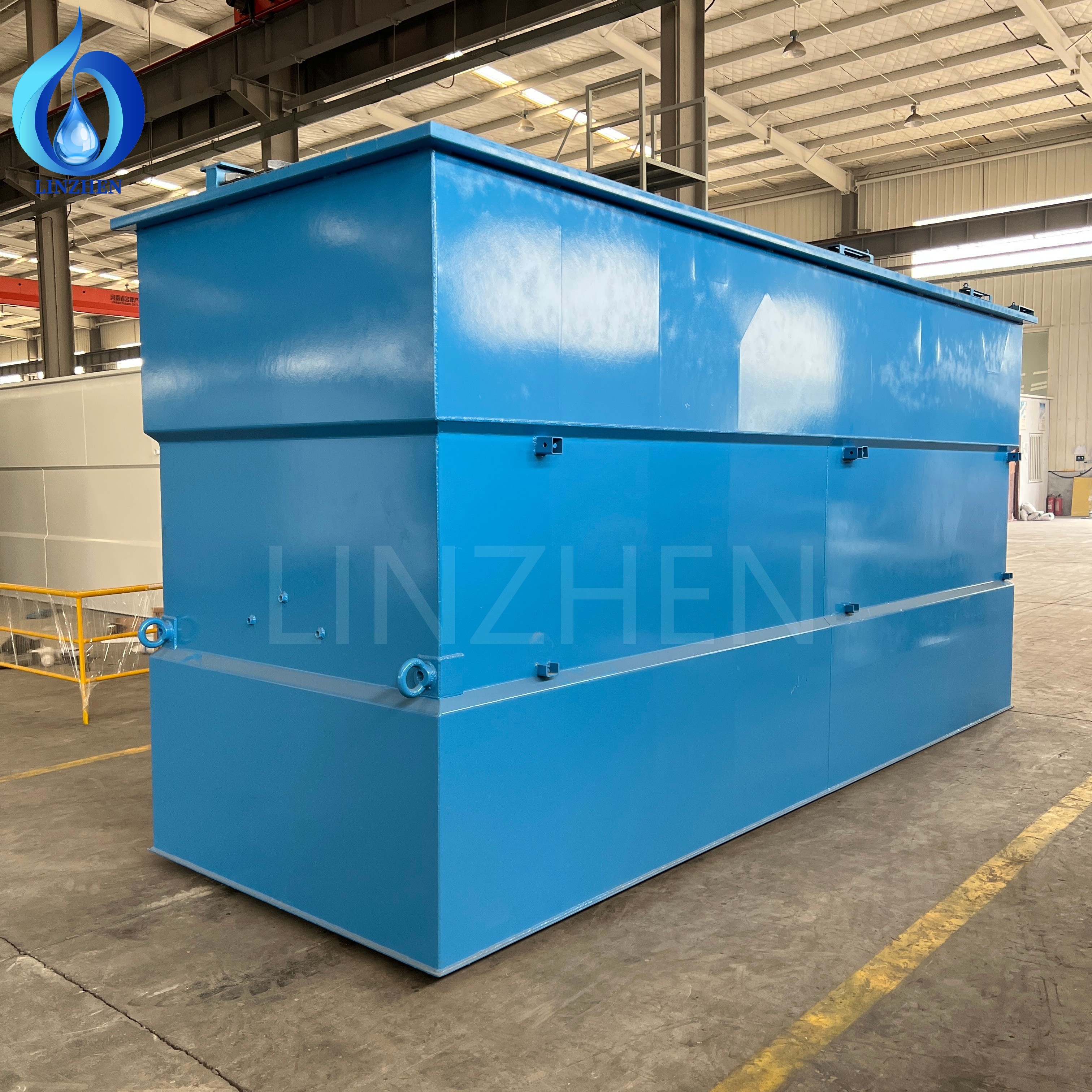
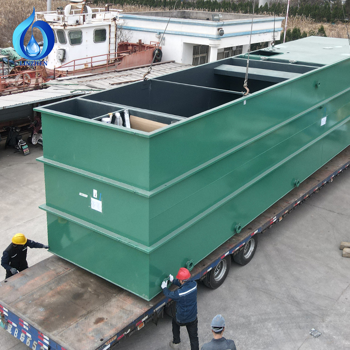
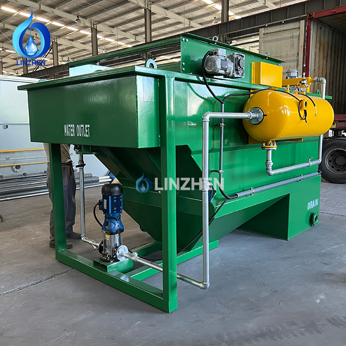
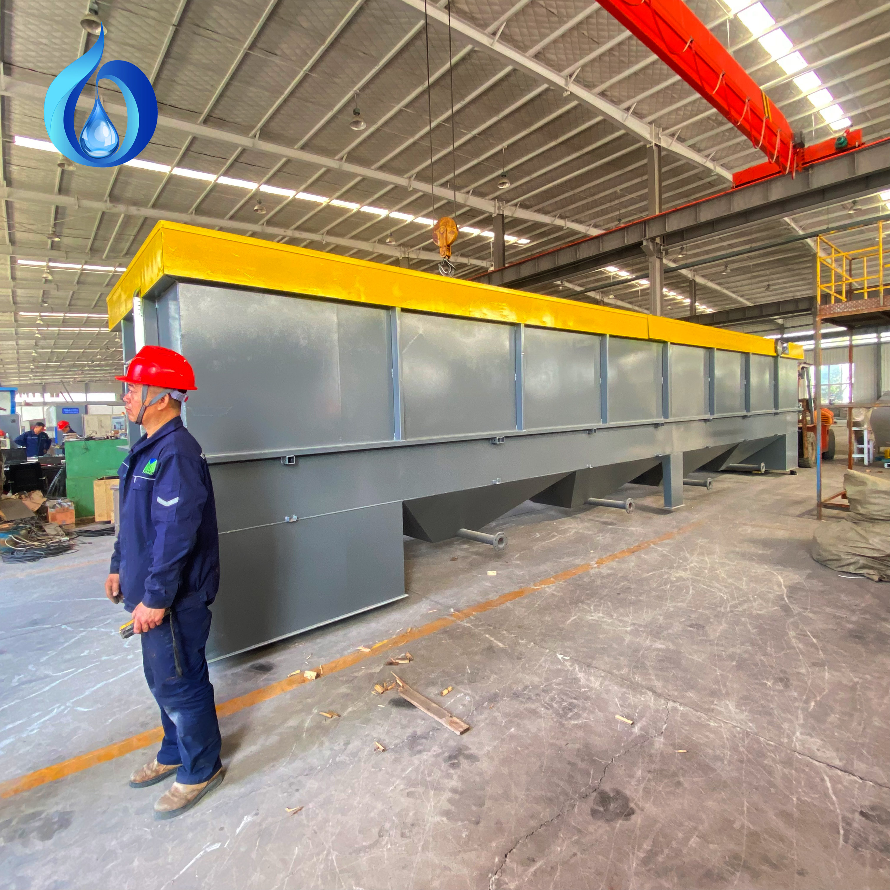
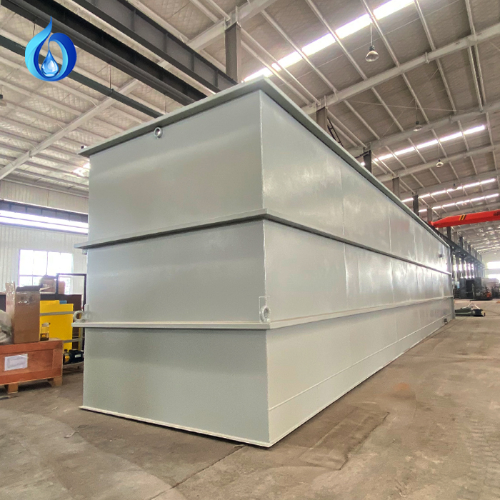
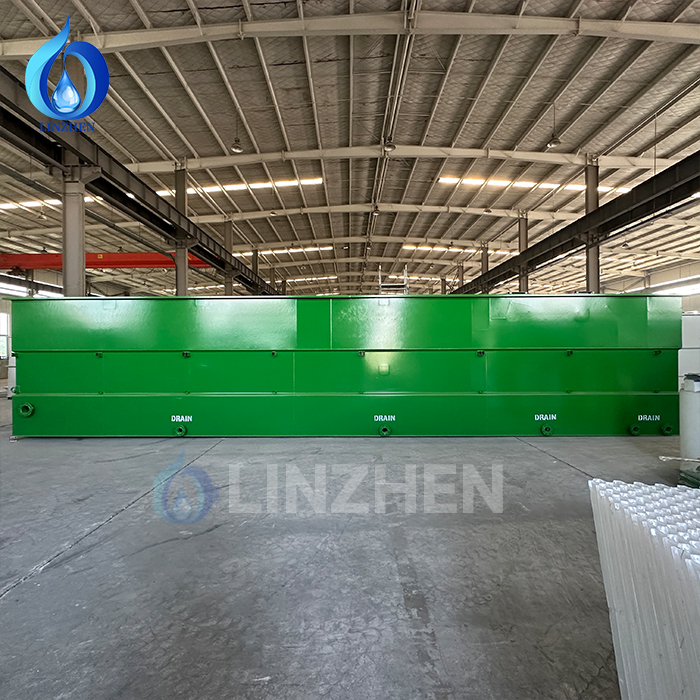
Basin architecture significantly affects how smoothly a DAF wastewater treatment unit separates buoyant solids from water. Rectangular basins with sloped hopper bottoms simplify sludge collection, whereas circular tanks save footprint space in tight spaces. The clarification zone of a DAF wastewater treatment vessel must offer adequate surface area for unhindered floc rise. Basin depths between 6 and 10 feet balance rise time against structural requirements. Maintaining length-to-width ratios between 2:1 and 4:1 in rectangular DAF wastewater treatment plants ensures uniform velocity distribution and eliminates dead zones.
Distribution Baffles and Mechanical Skimmers
Inlet baffles introduce incoming water evenly across the full width of the DAF wastewater treatment contact chamber, preventing localized turbulence. Properly positioned bottom outlets draw clarified water from below the floating sludge blanket, preventing solid carryover. Mechanical surface scrapers integrated into the DAF wastewater treatment design continuously collect floating scum without entraining free water. Heavy-duty scraper blades prevent sludge accumulation, guaranteeing consistent long-term DAF wastewater treatment operation even during high-load processing events.
FAQ
Which influent parameters most influence DAF wastewater treatment system sizing?
Peak hydraulic flow rate, total suspended solids concentration, FOG levels, and particle rise velocity are the primary factors governing DAF wastewater treatment system sizing. Each parameter directly dictates tank volume, air saturation pressure, residence time, and sludge removal mechanisms.
Why is residence time critical for DAF wastewater treatment efficiency?
Residence time gives micro-bubbles sufficient contact opportunity to attach to suspended particles and float them to the surface. Insufficient residence time in a DAF wastewater treatment tank results in incomplete separation and poor effluent quality, while excessive time increases capital costs without added benefit.
Can a standard DAF wastewater treatment unit handle variable flow spikes?
Yes, a properly sized DAF wastewater treatment system accommodates flow variations if designed with sufficient hydraulic safety margins and flexible air saturation equipment. Integrating equalization tanks upstream helps stabilize flow rates, ensuring predictable DAF wastewater treatment performance across all production cycles.
 EN
EN