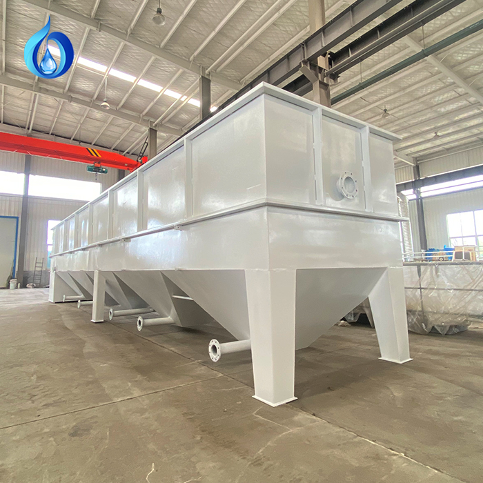
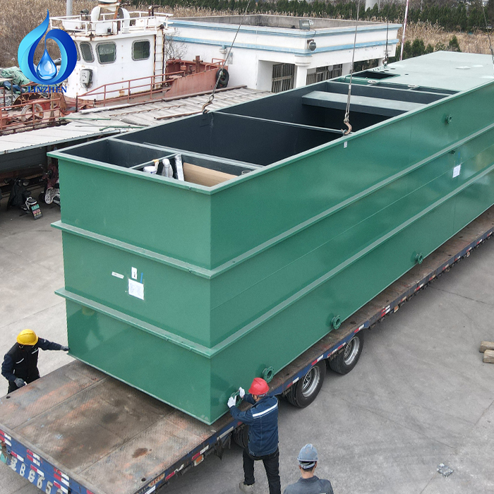
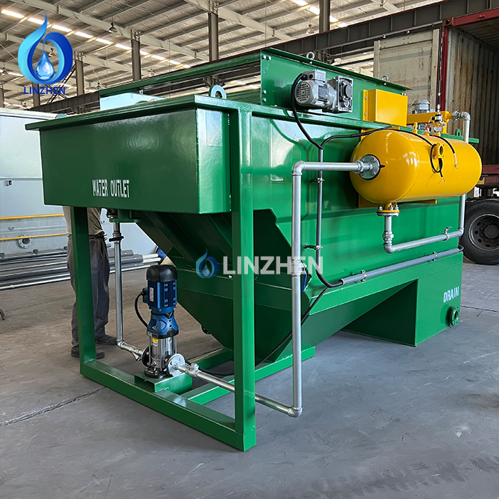
Achieving high-performance solids removal in municipal and industrial facilities depends heavily on accurate engineering, making lamella clarifier sizing a foundational step in liquid-solid separation design. An inclined plate settler uses stacked parallel plates to drastically increase total effective settling surface area within a compact physical footprint. Determining precise physical vessel dimensions ensures that the plant handles daily hydraulic loads without risking solids carryover or effluent turbidity spikes. This comprehensive guide details the key calculations and operational variables required for optimal lamella clarifier sizing.
Executing an effective lamella clarifier sizing procedure requires detailed knowledge of influent volumetric flow rates, total suspended solids (TSS) concentration, and targeted discharge quality. Inadequate lamella clarifier sizing causes poor clarification performance and premature basin overflow, whereas over-dimensioning wastes significant capital expenditure and structural real estate. Whether configuring a new municipal treatment facility or upgrading an industrial wastewater plant, engineers must carefully evaluate multiple interdependent design criteria during the initial lamella clarifier sizing phase.
Design Parameters Influencing Lamella Clarifier Sizing
Surface Loading Rate and Hydraulic Retention Time
The primary metric governing lamella clarifier sizing is the surface loading rate, expressed in gallons per minute per square foot (GPM/ft²) or cubic meters per hour per square meter. This factor represents the volume of water processed per unit of horizontal settling area over time. Most industrial units operate at a design surface loading rate between 2 and 5 GPM/ft². To determine the projected settling area required during lamella clarifier sizing, divide the total design flow by the target loading rate. For instance, a 500 GPM flow running at a 3 GPM/ft² loading rate requires roughly 167 square feet of effective settling area.
Equally important in lamella clarifier sizing is the hydraulic retention time (HRT), which dictates how long fluid resides inside the settling tank. Typical treatment systems maintain a hydraulic retention time of 20 to 45 minutes to facilitate gravity settling. Longer residence periods increase particle separation efficiency but demand larger tank volumes. Therefore, successful lamella clarifier sizing balances aggressive loading rates against a sufficient hydraulic retention time to deliver cost-effective performance within space-constrained environments.
Solids Concentration and Particle Settlement Characteristics
Influent solids loading directly shapes the physical outcome of lamella clarifier sizing. High suspended solids streams demand either larger plate surface areas or more frequent sludge evacuation cycles. Municipal primary influent usually ranges from 200 to 400 mg/L TSS, whereas heavy industrial streams often exceed 1,000 mg/L. When performing lamella clarifier sizing for high-solids applications, engineers must expand the lower hopper volume to prevent accumulated sludge from interfering with incoming fluid pathways along the inclined plates.
Particle size distribution also alters the entire lamella clarifier sizing model. Fine, light particles require conservative loading rates and longer residence times, which increases overall tank dimensions. Conversely, coarse particles settle rapidly, allowing higher hydraulic loading and more compact vessel profiles. Accurate lamella clarifier sizing for raw municipal effluent accounts for mixed particle sizes by utilizing conservative settling assumptions, whereas pretreated industrial streams allow for more aggressive inclined plate settler design parameters.
Calculations and Dimensioning in Inclined Plate Settler Design
Effective Settling Surface and Plate Configuration
Calculating total effective settling area is the central mathematical step in lamella clarifier sizing. Inclined plate packs are typically positioned at a 45 to 60-degree angle to enable gravity self-cleaning. To complete a precise wastewater clarifier calculation, engineers multiply the total number of plates by each plate's width and length, then apply a trigonometric correction factor based on the tilt angle. This multiplying effect allows an inclined plate settler design to yield massive settling capacity within a fraction of a traditional clarifier's footprint.
Plate spacing is another key parameter established during lamella clarifier sizing, typically ranging between 2 and 4 inches. Narrow plate gaps maximize total surface area, but overly tight spacing increases the risk of foulant clogging or floc shear. A standard 3-inch gap provides an optimal balance between spatial efficiency and operational maintainability. Finalizing your lamella clarifier sizing calculations involves verifying that plate materials and spacing accommodate periodic washing and ongoing chemical conditioning without fouling.
Hopper Depth and Effluent Weir Design
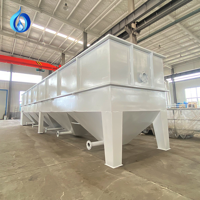
Vessel depth plays a major role in overall lamella clarifier sizing, affecting both clarification quality and sludge storage capacity. The upper plate clarification zone typically spans 5 to 8 feet, while the lower hopper section must hold settled sludge prior to dewatering. During lamella clarifier sizing, hopper depth is adjusted according to daily sludge production rates. Municipal plants with continuous pumping require a 3 to 4-foot hopper, while industrial batch operations may need a 6 to 8-foot storage cone, pushing total vessel height to 12 to 16 feet.
Effluent weir length must also be integrated into lamella clarifier sizing to ensure uniform liquid collection across the top of the tank. Overflow rates across V-notch weirs should stay under 3 GPM per linear foot to avoid pulling fine suspended solids back into the treated stream. This hydraulic requirement directly influences the top width and length calculated during lamella clarifier sizing, requiring multi-trough weir configurations for high-flow installations.
Operational Dynamics and Safety Margins in Lamella Clarifier Sizing
Managing Peak Flows and Hydraulic Surges
Fluctuating influent volumes introduce operational risks that must be addressed during lamella clarifier sizing. Municipal facilities contend with diurnal variations and storm-driven rainwater infiltration, while industrial plants experience batch discharge surges. A reliable lamella clarifier sizing strategy bases tank dimensions on peak hourly flow rather than average daily flow—often applying a 1.5x to 2.0x safety factor. This conservative design margin prevents hydraulic washout during unexpected flow spikes.
Including emergency bypass features is another best practice in lamella clarifier sizing. Secondary weir channels allow extreme storm surges to bypass the plate pack safely, preventing structural damage and keeping internal sludge blankets intact. Integrating these features into the early lamella clarifier sizing phase ensures that severe flow transients do not disrupt downstream filtration or biological processing units.
Coagulation, Flocculation, and Chemical Performance
Chemical conditioning directly influences lamella clarifier sizing requirements. Dosing coagulants like alum or ferric chloride upstream promotes the formation of large, dense flocs that settle rapidly. This accelerated settling velocity allows engineers to select a higher surface loading rate, effectively reducing the necessary lamella clarifier sizing footprint. Conversely, unconditioned colloidal wastewater requires lower loading rates and larger tank volumes.
Adding polymeric flocculants further improves floc shear resistance and settling velocity, boosting overall clarification throughput. During the initial lamella clarifier sizing evaluation, facility managers should weigh the capital cost of a larger physical tank against the ongoing operational cost of chemical conditioning. In most applications, a moderately sized unit paired with optimized chemical dosing delivers the most economical lifetime cost profile.
FAQ
What surface loading rate should be used for lamella clarifier sizing?
Standard lamella clarifier sizing uses a surface loading rate between 2 and 5 GPM/ft². Primary municipal applications typically target 2 to 3 GPM/ft², while industrial streams with fine solids may require rates below 2 GPM/ft² to prevent solids carryover.
How does hydraulic retention time affect lamella clarifier sizing?
The hydraulic retention time dictates the residence time needed for effective particle separation. Factoring a 20 to 45-minute residence window into your lamella clarifier sizing ensures sufficient time for solids to settle into the lower hopper collection zone.
Why is a wastewater clarifier calculation necessary when designing an inclined plate settler?
A precise wastewater clarifier calculation accounts for plate tilt angles, plate gaps, and effective surface multiplication. This math ensures that the inclined plate settler design achieves the required settling capacity within a small physical footprint.
 EN
EN